Saturday, January 24, 2015

L-band (Inmarsat, Thuraya, Iridium, GPS) filter

Decoding the data coming from the birds transmitting on the L-band became a new "sport" for cohort of the DVB-T dongle users, and not only. Tweaking the equipment for the best reception has always been a goal, mainly for the advanced users. Getting many requests for this kind of the filter I decide to compile a quick and short batch of the L-band SAT filter.


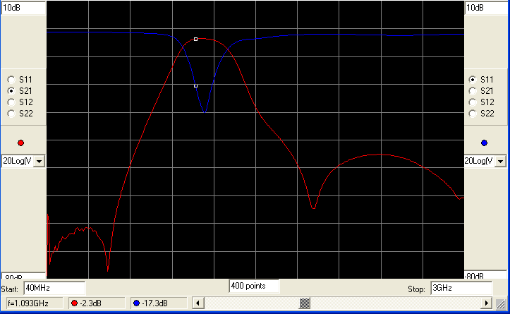
The main idea was to bring a small filter, with a descent bandpass shape and not big insertion loss. The filter using the same PCB as my other filters and the bias-t can be added (DIY) on the same board as well. Here is the simulation of the proposed filter. S2,1 and S1,1 can be seen on the graph together with the markers indicating the losses on a few spots of the interest.


Simulation showed a pass band -3dB bandwidth of 200kHz where most of the satellites are covered. The same filter can be also used for the Hydrogen line reception with a bit higher I.L. but still good for the second stage filter, running after the LNA frontend. The same filter can be used for Inmarsat, Thuraya, Iridium, GPS reception. Rejection of the out of the band signals is better on the lower frequencies, bellow the 1.3GHz. Rejection of the ADS-B radars, 965MHz cell, 825MHz LTE, TV and radio band is really good.  The rejection of the higher frequencies, 2450MHz Wi-Fi  is a bit lower but still good. The cell towers on 1.8-1.9GHz are not attenuated so much but still, 12.5dB, better than nothing. The simulation looking nice, but let's face the real world:


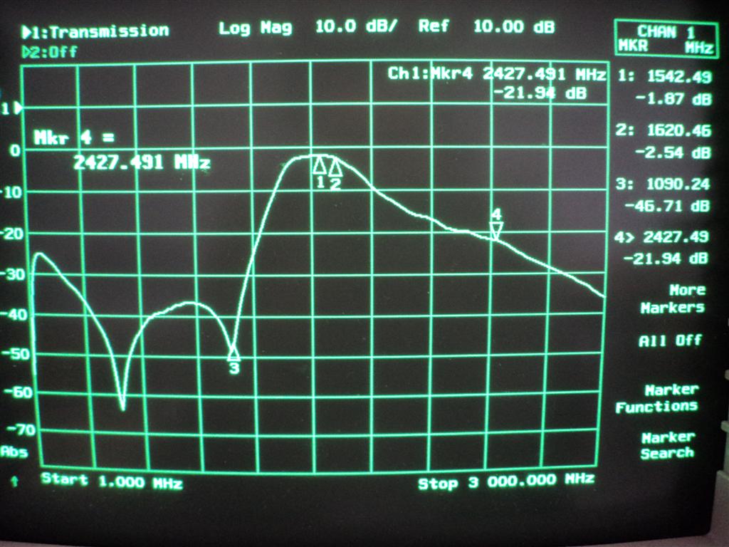
The S2,1 results are very close to he simulation. There is a small difference and the ripple in the 1.8-1.9GHz and the Wi-Fi 2450MHz region just because I had my mobile phone in the pocket, and Wi-Fi running on the same PC. The markers on the graph are clearly showing the I.L. on the 4 frequencies. For the guys that are not so friendly with the graph here are some figures, losses at the certain frequencies.

100 MHz - 25.88dB
820 MHz - 36.80dB
965 MHz - 38.10dB
1090 MHz - 46.70dB
1420 MHz - 2.67dB
1542 MHz - 1.87dB
1620 MHz - 2.56dB
1900 MHz - 12.50dB
2427 MHz - 21.90dB

Within the 3dB we have all satellite L-band channels and also the H-line frequency. The filter should be used after the LNA but if the strong blockers are present then the filter can be placed before the LNA. This will increase the noise figure for the insertion losses value but even this is small comparing to the bare DVB-T dongle noise figure. The users in the remote areas will not benefit using this filter but the users in the urban areas and close to the radio and TV towers may experience a big difference using the small filter described in this post.

The S1,1 or the RL in the passband can be seen on the following picture. Again, the real measurements are very close to the simulations. The simulations were done using the manufacturer S2p available data, so not including the SMA connectors nor the FR-4 1.2mm PCB.


Same  as the latest ADS-B filter, also this one comes with the Bias-T circuity on board. You can use the advantage of this feature and power supply the remote LNA placed on the antenna using the same coaxial cable used for the signal. The passband characteristic can allow also meteosat reception on 1700MHz with a bit higher I.L. but if remote LNA is used then this should work also OK. Check the measurements on the following video:


How does it perform in the "real life" check on the following video. Very common setup consisting of a simple antenna for the L-band and two LNA4ALL. In between there is a L-band filter.


We have this filters available with or without SMA fitted. Price 18 or 20 Euro, each.


Friday, January 23, 2015

Make your ADS-B reception even better

Running a ADS-B station on a hobby or semi-professional level can be fun. Better equipment results in more fun and more data received. Besides the good software, the quality hardware is a must if you want to go step further. One of the important aspects of the hardware is the RF front end design. If you run a factory product, dedicated ADS-B receiver or a cheap DVB-T dongle there is no room for a modification than can take you to the next step. The units are small and compact, plug and play.

The simple hardware addons can improve the performance resulting in more useful data received comparing to the barefoot hardware. One of addons that can do that are the filters. Depending of the situation, low pass, high pass or the bandpass filters are widely used. There are different ways how to approach to this problem. One way that I found is simple, cheap and affordable to everyday user.


So we are talking about filters. What we try to see from our filters is: low insertion loss, good out of the band signal rejection, good impedance matching, small size and a low price. The extra features should include non ESD device, DC through and a high power capability. Do we have such a filter? Too nice to be true!
I compile my own table of commonly used filter types and the features required. To make the things simpler I evaluate all the features as good, bad and smiley for a moderate.


It is obvious that "one in all" is difficult to get and the user should decide what is the best for him. If you are hobbyist then the price is important and should be on top of the list.


I made my choice and I design the filter that can be used for the ADS-B centered for the 1090 MHz operation. The simulation using the S parameters showing the attenuation in the pass band of 2.3dB. Not perfect but not the worst. The idea was to keep that value in the real prototype. Aside is the simulation of the filter designed for the ADS-B using the LTCC technology.


Available S parameters give us a range from 40Mhz up to 6GHz but I run my simulation up to 3GHz to cover the frequency range of interest. Next picture is the measurement done on the real filter. Quick look prove the design. More over the insertion losses in the pass band are also as predicted, or very close =  2.40dB despite using the SMA connectors not calculated in the simulation. Vertical scale i 10dB/divide and horizontal scale starting at 300kHz and ending at 3GHz.


The filter is not so sharp comparing to the SAW or cavity type filters but this is compromise that we have to count on. This filter is good if you want to "kill" the BC FM stations, TV signals, Wi-Fi signals, cell towers on 1.8GHz 1.9GHz 2.1GHz or higher. Cell towers on 950MHz will not be attenuated a lot, some 10-20dB, still the overall results are good. The picture clearly indicate the losses in the BC FM radio stations band of 100MHz. Attenuation is reaching -69dB.


Next important range of frequencies with the strong signals and blockers is the TV broadcast band. This signals are even stronger than the radio signals and closer to the ADS-B frequency. The highest attenuation is centered on 505MHz reaching -69dB. A bit lower the attenuation is -60dB and looking higher towards the 1GHz the attenuation is lower but still good -60 to -40dB.


Going further up to the Wi-Fi 2.4GHz frequency the attenuation is -45dB. The signals from the Wi-Fi are not so strong but they can be very close to your ADS-B reception antenna or system and it nice to have this band covered also. The attenuation between the Wi-Fi and the ADS-B is even better. This is where you can find the Cell towers operating on 1.8GHz, 1.9GHz and 2.1GHz.


There are two areas where the performance of the filter is not as on the other frequencies mentioned above. This are the Cell 950MHz and the possible radar interference on the 1.2-1.3GHz. As this frequencies are relatively close to the ADS-B 1090MHz the attenuation is not so big. It is better then nothing but not good as rejection that we can have with the cavity or some SAW filters design.

What you get? BASIC BOARD 

What you get is a bit different filter then the previous version. For the same price you get the ADS-B filter centered on 1090 MHz and a Bias-T ready board. The board can be used as a filter only using the SMA input/output or additionally the Bias-T power injector can be used too. The RF in-out ports are DC isolated so no DC pass through the filter. Maximum current allowed through the Bias-T is 150mA. The size of the PCB (FR-4 1.6mm thickness) is 20x15 mm and 39x15 mm with the two female SMA connectors soldered.


How to setup the ADS-B filter

1. Basic setup

As it says, the basic setup require just the ADS-B filter connected to the ADS-B receiver (or just a DVB-T dongle) using the jumper coaxial cable, or straight to the receiver antenna port with the adapter. The overall Noise Figure will be spoiled for the filter losses (2.4dB) but the benefit may be in filtering the strong out of the band "Blockers" and better reception. Filtering the blocker may allow increasing the DVB-T dongle gain, hence reducing the Noise Figure. The overall noise figure at the end may be even better than without the filter.

2. Setup with the LNA

Adding the LNA may improve the reception even more. More gain and lower Noise Figure will result better reception. The overall Noise Figure will be mainly depending on the LNA noise figure. The LNA can be powered directly or through the ADS-B filter Bias-T. Of course, the LNA should be adopted for Bias-T operation. Take care about the LNA voltage supply and maximum current allowed. Both the LNA and filter are close to the receiver (indoor).

3. Setup with the LNA *

At some point a very strong "Blockers" signals will push any LNA into the saturation where IMD products will be created spoiling the reception. To avoid that, the filter should be placed in front the LNA protecting the system from the unwanted signals leaving only the targeted signal. Such a filtered signal is then amplified in the chain. Both the LNA and filter are close to the receiver (indoor).

4. Remote LNA setup

If you live in the descent RF environment with not so strong signals then you may get the benefits of using the LNA close to the antenna . The filter can be close to the receiver as it will filter eventually picked up signals due to non perfect coaxial cable braid. The same ADS-B filter can be used also to power the remote LNA through the Bias-T.

Modifications
Plenty of them (coming soon) .....

You can check the performance using the filter from the next video. The filter was mounted after the LNA and showing improvement of about 20%. Inserting the filter before the LNA the performance can be even better, depending of the RF environment you are surrounded and the strong blockers in your vicinity.


I have just a limited number of the filters left and if you are interest please send me a mail.
Thanks


Tuesday, January 20, 2015

Hydrogen line 1420 MHz filter

After announcing the ADS-B filter we receive some inputs asking for other type of the filters. One of them is filter commonly used by the Radio astronomers for monitoring the Hydrogen line signals around 1420 MHz.
The filter described is made using the LTCC technology and is a compromise, same as the ADS-B filter.


The filter is built around the same PCB as the ADS-B filter using the 1.6mm FR-4 substrate and the same layout. The only difference is that there are no preassembled Bias-T parts leaving this option to buyers to complete if they need it requiring only one coil and three capacitors. The filter response is not so sharp and has the same characteristics as the ADS-B filter using the LTCC technology. The insertion losses on 1420 MHz are not so high, measured 2.5dB with the descent rejection of the unwanted frequencies. The real measurements match very closely to the designed ones and on the next diagram the red curve represent the shape and the characteristic of the 1420 MHz H-line bandpass filter.


The filter is designed to pass the 1420 MHz with the lowest insertion losses and at the same time to attenuate all other frequencies. he amount of attenuation is represented by the yellow bars. The longer bar - the higher attenuation. Vertical scale is 10dB/div and horizontal 300MHz/div.

Quickly going through the diagram, one may notice attenuation on the ADS-B radar frequency 1090 MHz of 37.5dB, GSM frequencies 865-965 MHz attenuated 36-38dB, LPD at 446MHz attenuated 62dB, Wi-Fi attenuated for 25dB. etc.

This filter is not designed to be a very first (front end) part of your receiver chain but it can be used just between the LNAs you are using. If the system is suffering from the strong TV, and GSM signals this filter can help you to get rid of this blockers a bit.


Monday, January 19, 2015

FLARM filter 868 MHz

Another growing interesting activity beside the ADS-B is also the FLARM. FLARM is collision avoidance system for general aviation but targeting the light aircraft's and UAVs. The frequency where the FLARM is operating cover the range from 868.0 up to 868.6 MHz. Very close to GSM bands and using only 10mW of ERP is not easy to detect, so the receivers with high LNA and narrow filters are required generally.

The FLARM filter I build will not protect the receiver from the nearby GSM signal but can help a lot filtering the rest strong signals coming from the radio and TV broadcast towers. The filter is built around the same PCB used for the ADS-B and H-line filter not including the Bias-T parts. If the Bias-T option is required, the user should add a few missing parts to have this option available too.


The filter response is not so sharp and has the same characteristics as the ADS-B filter using the LTCC technology. The measured insertion losses on 868 MHz are not so high, measured 2.0dB with the descent rejection of the unwanted frequencies. The real measurements match very closely to the designed ones and on the next diagram the red curve represent the shape and the characteristic of the 868 MHz FLARM bandpass filter.

The filter is designed to pass the 868 MHz with the lowest insertion losses and at the same time to attenuate all other frequencies. he amount of attenuation is represented by the yellow bars. The longer bar - the higher attenuation. Vertical scale is 10dB/div and horizontal 300MHz/div.

Quickly going through the diagram, one may notice attenuation on the radio WFM frequency 100 MHz of 62dB, GSM frequencies 1870 MHz attenuated 41.7dB, LPD at 446MHz attenuated 47dB, Wi-Fi attenuated for 35.7dB. etc. TV broadcasting band around 550MHz is attenuated 23.5dB and there is also some attenuation on the radar surveillance primary and secondary frequencies.

FLARM frequency range is very close to the 800MHz and 900MHz UMTS bands and it is very difficult to filter out this signals using such a cheap and simple filters. The UMTS bands 5 (824-849MHz and 869-894Mhz) and 6 (830-840MHz and 875-885MHz) are filled with the various mobile operators and a network of powerful transmitters so the miracles are not possible. On the other side, using this filters you will be able to filter all other signals that may cause you a headache when receiving a weak FLARM signals from the aircraft's.