Running a ADS-B station on a hobby or semi-professional level can be fun. Better equipment results in more fun and more data received. Besides the good software, the quality hardware is a must if you want to go step further. One of the important aspects of the hardware is the RF front end design. If you run a factory product, dedicated ADS-B receiver or a cheap DVB-T dongle there is no room for a modification than can take you to the next step. The units are small and compact, plug and play.
The simple hardware addons can improve the performance resulting in more useful data received comparing to the barefoot hardware. One of addons that can do that are the filters. Depending of the situation, low pass, high pass or the bandpass filters are widely used. There are different ways how to approach to this problem. One way that I found is simple, cheap and affordable to everyday user.

So we are talking about filters. What we try to see from our filters is: low insertion loss, good out of the band signal rejection, good impedance matching, small size and a low price. The extra features should include non ESD device, DC through and a high power capability. Do we have such a filter? Too nice to be true!
I compile my own table of commonly used filter types and the features required. To make the things simpler I evaluate all the features as good, bad and smiley for a moderate.

It is obvious that "one in all" is difficult to get and the user should decide what is the best for him. If you are hobbyist then the price is important and should be on top of the list.
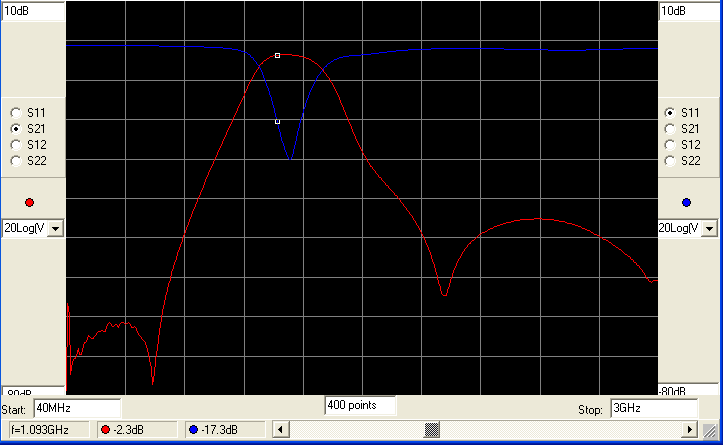
I made my choice and I design the
filter that can be used for the ADS-B centered for the 1090 MHz operation.
The simulation using the S parameters showing the attenuation in the
pass band of 2.3dB. Not perfect but not the worst. The idea was to keep that
value in the real prototype. Aside is the simulation of
the filter designed for the ADS-B using the LTCC technology.
.JPG) Available S parameters give us a range from 40Mhz up to 6GHz but I run
my simulation up to 3GHz to cover the frequency range of interest. Next
picture is the measurement done on the real filter. Quick look prove the
design. More over the insertion losses in the pass band are also as
predicted, or very close = 2.40dB despite using the SMA connectors not
calculated in the simulation. Vertical scale i 10dB/divide and horizontal scale starting at 300kHz and ending at 3GHz.
Available S parameters give us a range from 40Mhz up to 6GHz but I run
my simulation up to 3GHz to cover the frequency range of interest. Next
picture is the measurement done on the real filter. Quick look prove the
design. More over the insertion losses in the pass band are also as
predicted, or very close = 2.40dB despite using the SMA connectors not
calculated in the simulation. Vertical scale i 10dB/divide and horizontal scale starting at 300kHz and ending at 3GHz.


There are two areas where the performance of the filter is not as on the other frequencies mentioned above. This are the Cell 950MHz and the possible radar interference on the 1.2-1.3GHz. As this frequencies are relatively close to the ADS-B 1090MHz the attenuation is not so big. It is better then nothing but not good as rejection that we can have with the cavity or some SAW filters design.
What you get? BASIC BOARD
 What you get is a bit different filter then the previous version. For the same price you get the ADS-B filter centered on 1090 MHz and a Bias-T ready board. The board can be used as a filter only using the SMA input/output or additionally the Bias-T power injector can be used too. The RF in-out ports are DC isolated so no DC pass through the filter. Maximum current allowed through the Bias-T is 150mA. The size of the PCB (FR-4 1.6mm thickness) is 20x15 mm and 39x15 mm with the two female SMA connectors soldered.
How to setup the ADS-B filter
1. Basic setup

2. Setup with the LNA

3. Setup with the LNA *

4. Remote LNA setup

Modifications
Plenty of them (coming soon) .....
You can check the performance using the filter from the next video. The filter was mounted after the LNA and showing improvement of about 20%. Inserting the filter before the LNA the performance can be even better, depending of the RF environment you are surrounded and the strong blockers in your vicinity.
I have just a limited number of the filters left and if you are interest please send me a mail.
Thanks
"What an awesome post, I just read it from start to end. Learned something new after a long time
ReplyDeleteไพ่บาคาร่า "